
What a published study shows
In an ENTEGRA presentation, the PPSA 2025 seminar, Liuan Feng, Richard Desolner and Max Harrison compare the estimation of deformations by in-line measurements and laser scan. The general patterns are consistent, but the numerical values differ. The authors consider unsymmetric dents, several adjacent deluges and a combination of dents and obsolescence. Their main conclusion is that the curve calculation is useful for pre-selection, but complex geometry requires further analysis.
The reasons for the discrepancies are important for engineering assessment: reference surface, loading conditions and processing of measured profiles. Consider how these factors influence the calculation and selection of sites for additional control.
Deepness and deformation answer different questions
The depth of the dent describes the maximum surface deviation. It's convenient for a catalogue, but it doesn't contain all the local bend information. The floating depth and short folding may be the same, with radius of curvature and working conditions different. Therefore, longitudinal and district profiles are required for analysis, as well as a special provision for welds.
It is equally important to determine the reference surface: nominal cylinder, actual oval or section of the pipe before damage. The choice of this base affects the calculated form. If the obolity is automatically taken as part of a dent, then another description of the damage will be given than when two features are considered separately.
Why derivatives reinforce measurement errors
The curve is associated with the change of surface inclination. When she calculates it, a small error in the separate countdown can turn into a visible local peak. That is why the high density of points alone does not guarantee a reliable map of deformations. Information is needed on sensor accuracy, mechanic repeatability and smoothing algorithm.
Excessive smoothing creates the opposite problem: a sharp section becomes a spoon. A reasonable check includes several acceptable processing options and an assessment of the sustainability of the result. If the maximum changes significantly with a small change in filter parameters, it should be considered together with a range of uncertainty rather than as the only exact number.
The comparison of the two measurements starts with conditions
The laser scan after the excavation and the intra-bore profile before the excavation may describe the different states of one tube. External limitations change after removal of the ground or contact stone. The pressure during the examination also affects the shape. Therefore, the discrepancy does not always mean that one of the instruments is wrong.
The reference system, the circle orientation, the longitudinal reference and the surface area need to be agreed before comparison. The pressure, support state and method of obtaining the reference cylinder shall then be recorded. Only then does it make sense to compare depth, curvature and the calculated deformations. Otherwise, the properties of the instrument and the actual design change are mixed in one way.
Neighboring dents cannot be mechanically separated
Several delves may have a common transition area. If the algorithm cuts it into independent rectangles, each fragment will get artificial edges. If it unites too broadly, the local hazard zone is lost in a general context. The boundary of the object of analysis is therefore an engineering solution that must be reproducible.
It's useful to keep the original map and show exactly where the calculation plot is selected. For a complex shape, longitudinal sections in several angular positions are required, not just the profile through the deepest point. The maximum depth and maximum curvature may be placed in different locations; this change the choice of the additional control area.
From selection to more detailed model
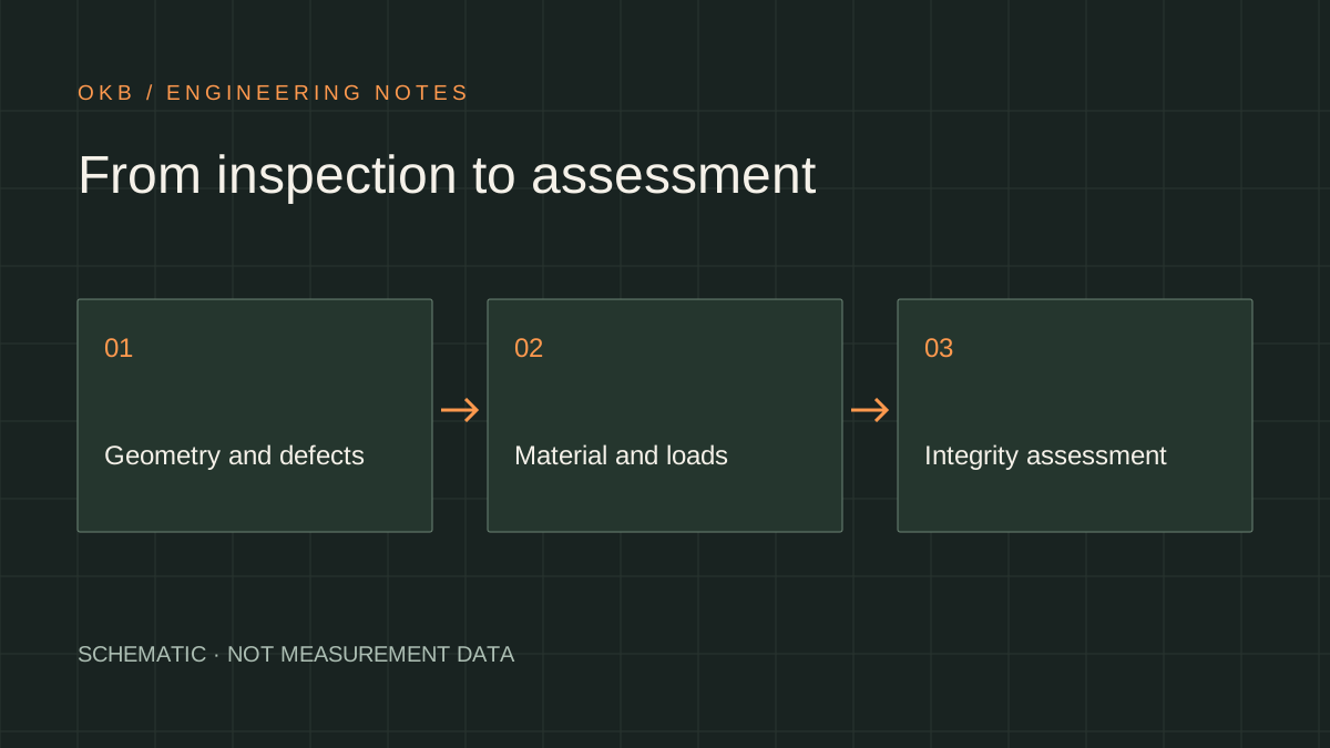
A simplified method allows for the identification of areas that deserve attention. A more complex model is required where its prerequisites do not reflect the actual form, contact or history of stress. When moving to the end-state calculation, geometry, material properties, wall thickness, boundary conditions and justification for load sequence are required.
The fact that the final elements are applied does not make the result true. The sensitivity to the grid, material version and contact conditions shall be checked. The map of deformations obtained should be accompanied by an explanation of what parameters are measured, which parameters are accepted in the documentation and which are investigated as a range of possible values.
What to Check When the Assessments Disparities
If two methods give substantially different maximums, it is useful to start with simple checks: whether the area is the same, do the units coincide, do the orientation change, and do not include the edge of the cut surface in the calculation? Then they look at the pressure and the conditions of the base. This procedure helps to separate the technical error of preparation from the substantive difference in models.
The reference surface and smoothing sensitivity shall then be checked. It is desirable to compare not only the maximum number but also the position of the extreme, the length of the zone and the reference sections. The convergence of the overall picture in a single peak would require a different interpretation than completely incompatible spatial results. In both cases, the explanation should be retained together with the final assessment.
What a useful report it should be
A good report links each final value to the original profile and processing phase. It separates the detection of dent, the measurement of shape, the calculation of deformations and the assessment of acceptability. These stages have different sources of uncertainty and should not be merged into one "fine" mark.
This is a specific task for the caliper tool developer: to ensure stable geometry of the measuring system, to maintain reliable coordinates and to keep the baseline accounts. For the meter — Clearly, to ask the application area of the chosen method. The joint work becomes convincing when another specialist can restore the course of analysis and understand the reasons for the final decision.
Engineering output
In the evaluation of dents, not only depth is important, but also shape, measurement conditions and sustainability of calculation. The methods should be compared on a harmonized geometric and load base.
Sources and further reading
- PPSA Technical Report 2025open PDFENTEGRA — Method to the Madness: Why Assessment Technique Matters when Inspecting Dent Strain ↗
The article was originally written in Russian. It summarises the cited sources. For the original text and illustrations, consult the publications listed below.